GMAC
介绍 K3 GMAC 的功能和使用方法。
模块介绍
K3 GMAC 模块基于 Synopsys DesignWare Ethernet QoS 控制器(版本 5.40a),符合 IEEE 802.3-2015 标准,支持 10/100/1000 Mbps 速率通信和多种高级网络特性,适用于 AV 桥接、交换机、网卡及数据中心网络设备等应用场景。
功能介绍
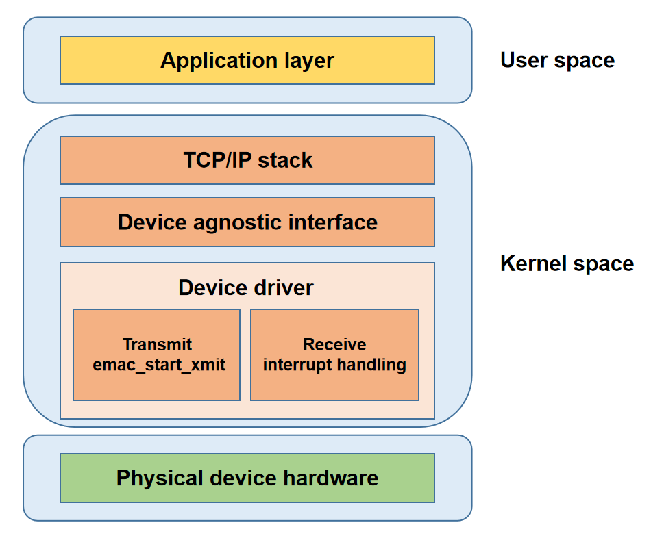
- 应用层: 面向用户提供应用服务。
- 协议栈层: 实现网络协议,为应用层提供系统调用接口。
- 网络设备抽象层: 屏蔽驱动实现细节,为协议栈提供统一接口。
- 网络设备驱动层: 负责实现数据传输和设备管理。
- 物理层: 网络硬件设备。
源码结构介绍
驱动源码位于 drivers/net/ethernet/stmicro/stmmac 目录,主要文件如下:
drivers/net/ethernet/stmicro/stmmac
|-- ...
|-- dwmac-spacemit-ethqos.c         # Spacemit 平台 EQoS glue 层驱动
|-- ...
关键特性
| 特性 | 特性说明 |
|---|---|
| 支持 MII/RMII/RGMII 接口 | 支持多种 PHY 接口 |
| 支持 10/100/1000 Mbps | 支持多种通信速率 |
| 支持 Jumbo 帧 | 支持最大 8KB 以太网帧 |
| 支持源地址插入与替换 | 自动填充或修改源 MAC 地址 |
| 支持 VLAN 标签插入/替换/删除 | 硬件处理 VLAN 标签 |
| 支持 VLAN 过滤 | 基于 VLAN ID 过滤报文 |
| 支持目的地址过滤 | 基于目的 MAC 过滤报文 |
| 支持源地址过滤 | 基于源 MAC 过滤报文 |
| 支持 Hash 过滤 | 基于 MAC 地址哈希值过滤报文 |
| 支持 L3 过滤 | 基于 IP 地址过滤报文 |
| 支持 L4 过滤 | 基于 TCP/UDP 端口号过滤报文 |
| 支持 IEEE 802.3x Pause | 支持 Pause 帧流控机制 |
| 支持 PFC | 支持优先级流控 |
| 支持 one-step 时间戳 | 时间戳嵌入同步报文 |
| 支持一路 PPS 输出 | 基于硬件时钟输出脉冲信号 |
| 支持 WoL | 支持网络唤醒 |
| 支持 MAC 环回模式 | 用于接口自检和调试定位 |
| 支持可编程突发长度 | 可配置 AXI 突发传输 |
| 支持最多 4 个 TX/RX 队列 | 支持多队列调度与分流 |
| 支持 Store-and-Forward | 整帧在 FIFO 中缓存后再传输 |
| 支持 Threshold 模式 | FIFO 中数据达到阈值即传输 |
| 支持 SP 调度 | 严格优先级调度 |
| 支持 WRR 调度 | 加权轮询调度 |
| 支持 DWRR 调度 | 差额加权轮询调度 |
| 支持 WFQ 调度 | 公平队列调度 |
| 支持 CBS | 信用整形调度 |
| 支持 EST | 时间门控调度 |
| 支持帧抢占 | 高优先级帧可抢占低优先级帧 |
| 支持 TBS | 基于硬件时钟的精确调度 |
| 支持最多 4 个 DMA 通道 | 多通道并行传输 |
| 支持 TSO | 硬件分段 TCP 报文 |
| 支持 IPv4 校验和卸载 | 硬件计算 IPv4 校验和 |
| 支持 TCP 校验和卸载 | 硬件计算 TCP 校验和 |
| 支持 UDP 校验和卸载 | 硬件计算 UDP 校验和 |
| 支持 ICMP 校验和卸载 | 硬件计算 ICMP 校验和 |
| 支持头/载荷分离存储 | 以太网协议头和数据分开存储 |
| 支持 ARP 卸载 | 硬件响应 ARP 请求 |
| 支持 CRC 卸载 | 硬件自动生成和校验 CRC |
| 支持按优先级分流 | 按优先级分配通道 |
注: K3 平台支持四路 GMAC(GMAC0-GMAC3),仅 GMAC0/GMAC1 完整支持 MII/RMII/RGMII 接口;GMAC2/GMAC3 仅支持 RGMII/RMII 接口。
性能参数
吞吐
| 协议 | 测试模式 | Tx 吞吐(Mbps) | Rx 吞吐(Mbps) |
|---|---|---|---|
| TCP | 单向传输 | 942 | 941 |
| TCP | 双向传输 | 935 | 934 |
| UDP | 单向传输 | 956 | 956 |
| UDP | 双向传输 | 956 | 955 |
PTP 同步精度
| 协议 | 时间戳方式 | 稳态同步精度 |
|---|---|---|
| IEEE 802.3/L2 | 硬件时间戳 | < 250 ns |
| UDP/IPv4 | 硬件时间戳 | < 250 ns |
注: 双向打流情形下测试吞吐具有一定波动
性能测试
吞吐测试
测试设备: 2 块 k3 deb1 板,分别记为 deb1 A、deb1 B
网络拓扑: deb1 A、deb1 B 的千兆网口通过网线直连
环境要求: deb1 A、deb1 B 需安装 iperf3
Step1: 2 块板子千兆网口 IP 地址配置在同一网段,deb1 A 启动 iperf3 服务端
# deb1 A shell: set interface IP to 192.168.0.1
ifconfig end0 192.168.0.1 netmask 255.255.255.0

# deb1 A shell: start iperf3 server
iperf3 -s -B 192.168.0.1
# deb1 B shell: set interface IP to 192.168.0.2
ifconfig end0 192.168.0.2 netmask 255.255.255.0
Step2: deb1 B 启动 iperf3 客户端
测试项1: 基于 TCP 协议单向打流
# deb1 B shell: test TCP TX throughput
iperf3 -c 192.168.0.1 -B 192.168.0.2 -t 60
# deb1 B shell: test TCP RX throughput
iperf3 -c 192.168.0.1 -B 192.168.0.2 -t 60 -R
测试项2: 基于 TCP 协议双向打流
# deb1 B shell: test TCP full-duplex throughput
iperf3 -c 192.168.0.1 -B 192.168.0.2 -t 100 --bidir
测试项3: 基于 UDP 协议单向打流
# deb1 B shell: test UDP TX throughput
iperf3 -c 192.168.0.1 -B 192.168.0.2 -u -b 1000M -t 60
# deb1 B shell: test UDP RX throughput
iperf3 -c 192.168.0.1 -B 192.168.0.2 -u -b 1000M -t 60 -R
测试项4: 基于 UDP 协议双向打流
# deb1 B shell: test UDP full-duplex throughput
iperf3 -c 192.168.0.1 -B 192.168.0.2 -u -b 1000M -t 60 --bidir
PTP测试
测试设备: 2 块 k3 deb1 板,分别记为 deb1 A、deb1 B
网络拓扑: deb1 A、deb1 B 的千兆网口通过网线直连
环境要求: deb1 A、deb1 B 需安装 linuxptp
测试项1: 基于 L2 以太网帧进行时间同步
# deb1 A shell: start PTP master over L2 Ethernet frames
ptp4l -i end0 -2 -H -m
# deb1 B shell: start PTP slave over L2 Ethernet frames
ptp4l -i end0 -2 -H -m -s
测试项2: 基于 UDP/IPv4 进行时间同步
# deb1 A shell: set interface IP to 192.168.0.1
ifconfig end0 192.168.0.1 netmask 255.255.255.0

# deb1 A shell: start PTP master over UDP/IPv4
ptp4l -i end0 -4 -H -m

# deb1 B shell: set interface IP to 192.168.0.2
ifconfig end0 192.168.0.2 netmask 255.255.255.0

# deb1 B shell: start PTP slave over UDP/IPv4
ptp4l -i end0 -4 -H -m -s
功能测试
这里主要测试 TSN 功能
测试设备: 2 块 k3 deb1 板,分别记为 deb1 A、deb1 B
网络拓扑: deb1 A、deb1 B 的千兆网口通过网线直连
环境要求 deb1 A 需安装 iperf3、tcpdump; deb1 B 需安装 iperf3、netsniff-ng、linuxptp、ethtool
Step1: 2 块板子千兆网口 IP 地址配置在同一网段
# deb1 A shell: set interface IP to 192.168.0.1
ifconfig end0 192.168.0.1 netmask 255.255.255.0

# deb1 B shell: set interface IP to 192.168.0.2
ifconfig end0 192.168.0.2 netmask 255.255.255.0
Step2: 在 deb1 B 端同步系统时间和 GMAC 硬件时间
# deb1 B shell: /dev/ptp1 is the PTP clock node for end0
phc2sys -s /dev/ptp1 -c CLOCK_REALTIME -O 0 -m > ptp.txt 2>&1 &

# deb1 B shell: check sync accuracy is below 1 us
tail -n 10 ptp.txt
期望结果: CLOCK_REALTIME phc offset < 1000, 如下
phc2sys[137.942]: CLOCK_REALTIME phc offset       -51 s2 freq     +28 delay    250
phc2sys[138.942]: CLOCK_REALTIME phc offset       -12 s2 freq     +52 delay    291
phc2sys[139.942]: CLOCK_REALTIME phc offset        29 s2 freq     +90 delay    291
phc2sys[140.943]: CLOCK_REALTIME phc offset      -101 s2 freq     -32 delay    291
phc2sys[141.943]: CLOCK_REALTIME phc offset       101 s2 freq    +140 delay    291
phc2sys[142.943]: CLOCK_REALTIME phc offset       -21 s2 freq     +48 delay    292
phc2sys[143.943]: CLOCK_REALTIME phc offset        32 s2 freq     +95 delay    291
phc2sys[144.944]: CLOCK_REALTIME phc offset       -85 s2 freq     -12 delay    291
phc2sys[145.944]: CLOCK_REALTIME phc offset        36 s2 freq     +83 delay    291
phc2sys[146.944]: CLOCK_REALTIME phc offset        10 s2 freq     +68 delay    292
Step3: 用 tc 工具配置门控调度算法,因 K3 默认配置 2 个 TX 队列,下面脚本配置 2 个 TC,并分别映射到 2 个 TX 队列
#!/bin/sh

NOW=$(date +%s)
BASE_TIME=$((NOW + 2))
NOW_NS=$((BASE_TIME * 1000000000))
echo "Base Time (ns): $NOW_NS"

tc qdisc replace dev end0 parent root stab overhead 24 linklayer ethernet taprio \
    num_tc 2 \
    map 0 0 0 0 0 0 0 1 \
    queues 1@0 1@1 \
    base-time $NOW_NS \
    sched-entry S 0x2 50000 \
    sched-entry S 0x1 450000 \
    fp P E \
    flags 0x2
Step4: 开启 FPE,并等待验证完成
# deb1 A shell: enable FPE
ethtool --set-mm end0 pmac-enabled on tx-enabled on verify-enabled on verify-time 128

# deb1 B shell: enable FPE
ethtool --set-mm end0 pmac-enabled on tx-enabled on verify-enabled on verify-time 128
开启后等待1-2分钟时间,让硬件进行一个 Verification
ethtool --show-mm end0
期望结果:
MAC Merge layer state for end0:
pMAC enabled: on
TX enabled: on
TX active: on
TX minimum fragment size: 60
RX minimum fragment size: 60
Verify enabled: on
Verify time: 128
Max verify time: 128
Verification status: SUCCEEDED
Step5: 利用 iperf3 制造背景流量
# deb1 A shell: start iperf3 server on deb1 A
iperf3 -s -B 192.168.0.1

# deb1 B shell: start iperf3 client on deb1 B
iperf3 -c 192.168.0.1 -B 192.168.0.2 -t 10000
Step6: 利用 mausezahn 制造关键流量
# deb1 B shell: start critical traffic with priority=7, UDP=5000, payload=18B, period=1 ms
sudo mausezahn end0 -q -c 0 -d 1000 \
  -R 7 \
  -a own \
  -b 50:0a:52:0b:ca:26 \
  -A 192.168.0.2 \
  -B 192.168.0.1 \
  -t udp "sp=4000,dp=5000" \
  -P "CCCCCCCCCCCCCCCCCC"
Step7: 在 deb1 A 端抓关键流量包,间隔应当在 1ms 左右
sudo tcpdump -i end0 -e -n \
  'udp and src host 192.168.0.2 and dst host 192.168.0.1 and src port 4000 and dst port 5000 and less 100'
输出结果:
tcpdump: verbose output suppressed, use -v[v]... for full protocol decode
listening on end0, link-type EN10MB (Ethernet), snapshot length 262144 bytes
17:30:55.691980 fe:fe:fe:ec:26:7c > 50:0a:52:0b:ca:26, ethertype IPv4 (0x0800), length 60: 192.168.0.2.4000 > 192.168.0.1.5000: UDP, length 18
17:30:55.692981 fe:fe:fe:ec:26:7c > 50:0a:52:0b:ca:26, ethertype IPv4 (0x0800), length 60: 192.168.0.2.4000 > 192.168.0.1.5000: UDP, length 18
17:30:55.693982 fe:fe:fe:ec:26:7c > 50:0a:52:0b:ca:26, ethertype IPv4 (0x0800), length 60: 192.168.0.2.4000 > 192.168.0.1.5000: UDP, length 18
17:30:55.694980 fe:fe:fe:ec:26:7c > 50:0a:52:0b:ca:26, ethertype IPv4 (0x0800), length 60: 192.168.0.2.4000 > 192.168.0.1.5000: UDP, length 18
17:30:55.695978 fe:fe:fe:ec:26:7c > 50:0a:52:0b:ca:26, ethertype IPv4 (0x0800), length 60: 192.168.0.2.4000 > 192.168.0.1.5000: UDP, length 18
17:30:55.697398 fe:fe:fe:ec:26:7c > 50:0a:52:0b:ca:26, ethertype IPv4 (0x0800), length 60: 192.168.0.2.4000 > 192.168.0.1.5000: UDP, length 18
17:30:55.698398 fe:fe:fe:ec:26:7c > 50:0a:52:0b:ca:26, ethertype IPv4 (0x0800), length 60: 192.168.0.2.4000 > 192.168.0.1.5000: UDP, length 18
17:30:55.699398 fe:fe:fe:ec:26:7c > 50:0a:52:0b:ca:26, ethertype IPv4 (0x0800), length 60: 192.168.0.2.4000 > 192.168.0.1.5000: UDP, length 18
17:30:55.700396 fe:fe:fe:ec:26:7c > 50:0a:52:0b:ca:26, ethertype IPv4 (0x0800), length 60: 192.168.0.2.4000 > 192.168.0.1.5000: UDP, length 18
17:30:55.701398 fe:fe:fe:ec:26:7c > 50:0a:52:0b:ca:26, ethertype IPv4 (0x0800), length 60: 192.168.0.2.4000 > 192.168.0.1.5000: UDP, length 18
17:30:55.702397 fe:fe:fe:ec:26:7c > 50:0a:52:0b:ca:26, ethertype IPv4 (0x0800), length 60: 192.168.0.2.4000 > 192.168.0.1.5000: UDP, length 18
17:30:55.703397 fe:fe:fe:ec:26:7c > 50:0a:52:0b:ca:26, ethertype IPv4 (0x0800), length 60: 192.168.0.2.4000 > 192.168.0.1.5000: UDP, length 18
注::这里的测量是一个粗糙测量,tcpdump是在协议栈抓取的包,具备一定误差,精确测量需专用的 TSN 协议分析仪抓线上数据
配置介绍
主要包括 Kconfig 配置 和 DTS 配置
Kconfig 配置
DWMAC_SPACEMIT_ETHQOS:启用 SpacemiT 的 EQoS 控制器驱动
config DWMAC_SPACEMIT_ETHQOS
        tristate "Spacemit ETHQOS support"
        depends on OF && (SOC_SPACEMIT || COMPILE_TEST)
        help
          Support for the Spacemit ETHQOS core.

          This selects the Spacemit ETHQOS glue layer support for the
          stmmac device driver.
DTS 配置
pinctrl
GMAC 的 pin 配置取决于板级硬件设计。在 k3-pinctrl.dtsi 中,GMAC 相关 pin 已按功能完成分组。以 GMAC0 为例:
gmac0_base_pins:基础 pin 组,RMII 模式直接使用gmac0_rgmii_add_pins:RGMII 模式相对基础 pin 组补充的 pingmac0_mii_add_pins:MII 模式相对 RGMII 模式补充的 pingmac0_int_pins:PHY 中断引脚。部分 PHY 可在链路状态变化或唤醒事件发生时输出中断信号(可选)gmac0_pps_pins:PPS(每秒脉冲,Pulse Per Second)信号输出引脚(可选)gmac0_refclk_pins:25M 参考时钟输出引脚,用于为 PHY 提供工作时钟(可选)
上述 pin 的 function 均配置为 1,表示复用为 GMAC 功能。
gmac0_cfg: gmac0-cfg {
	/* Base pins: - Used by RMII directly */
	gmac0_base_pins: gmac0-0-pins {
		pinmux = <K3_PADCONF(0, 1)>, /* gmac0: MII=rxdv | RMII=crs_dv | RGMII=rx_ctl */
			 <K3_PADCONF(1, 1)>,     /* gmac0 rx d0 */
			 <K3_PADCONF(2, 1)>,     /* gmac0 rx d1 */
			 <K3_PADCONF(3, 1)>,     /* gmac0: MII=rxc | RMII=ref_clk | RGMII=rxc */
			 <K3_PADCONF(6, 1)>,     /* gmac0 tx d0 */
			 <K3_PADCONF(7, 1)>,     /* gmac0 tx d1 */
			 <K3_PADCONF(11, 1)>,    /* gmac0: MII=tx_en | RMII=tx_en | RGMII=tx_ctl */
			 <K3_PADCONF(12, 1)>,    /* gmac0 mdc */
			 <K3_PADCONF(13, 1)>;    /* gmac0 mdio */

		bias-disable;                /* normal bias disable */
		drive-strength = <9>;	     /* DS4 */
	};

	/* RGMII extra pins: add on top of base pins */
	gmac0_rgmii_add_pins: gmac0-1-pins {
		pinmux = <K3_PADCONF(4, 1)>, /* gmac0 rx d2 */
			 <K3_PADCONF(5, 1)>,     /* gmac0 rx d3 */
			 <K3_PADCONF(8, 1)>,     /* gmac0 tx clk */
			 <K3_PADCONF(9, 1)>,     /* gmac0 tx d2 */
			 <K3_PADCONF(10, 1)>;    /* gmac0 tx d3 */

		bias-disable;                /* normal bias disable */
		drive-strength = <9>;	     /* DS4 */
	};

	/* MII extra pins: add on top of (base + rgmii extra pins) */
	gmac0_mii_add_pins: gmac0-2-pins {
		pinmux = <K3_PADCONF(15, 1)>, /* gmac0 rxer */
			 <K3_PADCONF(16, 1)>,     /* gmac0 txer */
			 <K3_PADCONF(17, 1)>,     /* gmac0 crs */
			 <K3_PADCONF(18, 1)>;     /* gmac0 col */

		bias-disable;                 /* normal bias disable */
		drive-strength = <9>;	     /* DS4 */
	};

	/* Optional int pins */
	gmac0_int_pins: gmac0-3-pins {
		pinmux = <K3_PADCONF(14, 1)>; /* gmac0 int (from phy) */

		bias-disable;                 /* normal bias disable */
		drive-strength = <9>;	     /* DS4 */
	};

	/* Optional pps pins */
	gmac0_pps_pins: gmac0-4-pins {
		pinmux = <K3_PADCONF(19, 1)>; /* gmac0 pps (tsn/1588) */

		bias-disable;                 /* normal bias disable */
		drive-strength = <9>;	     /* DS4 */
	};

	/* Optional reference clock output */
	gmac0_refclk_pins: gmac0-5-pins {
		pinmux = <K3_PADCONF(20, 1)>; /* gmac0 clk ref */

		bias-disable;                 /* normal bias disable */
		drive-strength = <9>;	     /* DS4 */
	};
};
实际配置时,需根据板级硬件设计选择对应的 pinmux 组。以 K3 deb1 为例,该板采用 GMAC0 外接 RGMII PHY,PHY 工作时钟由外部晶振提供,未使能 GMAC0 PPS 输出,亦未启用 PHY 中断,IO 电压域为 1.8 V。基于该硬件设计,方案 DTS 中可删除 gmac0-2-pins、gmac0-4-pins 和 gmac0-5-pins,并通过 power-source 属性设置 pin 电压阈为 1.8 V。
&pinctrl {
	gmac0-cfg {
		/delete-node/ gmac0-2-pins;     //释放不需要的 pin,这些 pin 可能被其他模块使用
		/delete-node/ gmac0-4-pins;
		/delete-node/ gmac0-5-pins;

		gmac0-0-pins {
			power-source = <1800>;      //应当与实际 IO 供电一致,否则可能导致 IO 电流倒灌或无法正常工作
		};

		gmac0-1-pins {
			power-source = <1800>;
		};

		gmac0-3-pins {
			power-source = <1800>;
		};

		/**
		 * 新增 PHY 复位引脚配置。
		 * 该引脚的 function 配置为 0,复用为 GPIO,
		 * 用于控制 PHY 的硬件复位,详见下一小节。
		 */
		gmac0-6-pins {
			pinmux = <K3_PADCONF(15, 0)>;

			bias-disable;
			drive-strength = <25>;
			power-source = <1800>;
		};
	};
}
然后在板级 DTS 的以太网节点引用 pin 配置即可
ð0 {
pinctrl-names = "default";
pinctrl-0 = <&gmac0_cfg>;
...
}
gpio
查看开发板原理图,确认以太网 PHY 复位信号对应的 GPIO。以 K3 deb1 为例,该板用于 PHY 复位的控制引脚为 GPIO15。除完成该引脚的 function 配置外(详见上节),还需在板级 DTS 的 eth0 节点中增加复位相关属性:
ð0 {
...
snps,reset-gpios = <&gpio 0 15 GPIO_ACTIVE_LOW>;
snps,reset-delays-us = <0 20000 100000>;
...
}
其中,复位保持时间为 20us,解除复位后的等待时间为 100us,具体时序参数应满足对应 PHY 芯片手册要求。
phy 配置
phy 相关的配置主要有 phy-mode、phy-handle、phy 子节点。在 phy 子节点中通过 compatible 中的 PHY ID 完成设备匹配,同时需可通过 reg 属性配置 phy address 以及提供可选的 LED 配置,以k3 deb1 为例,其配置如下:
ð0 {
...
phy-mode = "rgmii";
phy-handle = <&gmac0_phy>;
...
mdio {
#address-cells = <1>;
#size-cells = <0>;
compatible = "snps,dwmac-mdio";
gmac0_phy: ethernet-phy@1 {
compatible = "ethernet-phy-id001c.c916",
"ethernet-phy-ieee802.3-c22";
reg = <1>;
leds {
#address-cells = <1>;
#size-cells = <0>;
led@1 {
reg = <1>;
function = LED_FUNCTION_LAN;
color = <LED_COLOR_ID_GREEN>;
default-state = "keep";
};
led@2 {
reg = <2>;
function = LED_FUNCTION_LAN;
color = <LED_COLOR_ID_YELLOW>;
default-state = "keep";
};
};
};
}
...
};
TX phase 和 RX phase
在 RGMII 接口下,时钟与数据信号的相位偏差会受板级 PCB 布线影响,严重时可能导致 PHY 采样错误。K3 平台支持配置时钟相位偏移,以优化采样窗口,确保满足严苛的时序约束(Setup/Hold Margin)。以 K3 Deb1 为例,配置如下:
ð0 {
...
spacemit,clk-tuning-enable;
spacemit,clk-tuning-by-delayline;
spacemit,tx-phase = <73>;
spacemit,rx-phase = <61>;
...
};
其中,spacemit,clk-tuning-enable 用于使能 K3 平台的时钟相位调节功能。对于部分 PHY,如 RMII、MII 接口类型 PHY,通常无需启用该功能;另外若由 PHY 侧提供 delay,也无需在 K3 侧重复配置。当相位调节由 K3 侧承担时,进一步可分为以下三种方式:
spacemit,clk-tuning-by-reg
spacemit,clk-tuning-by-delayline
spacemit,clk-tuning-by-clk-revert
注意 spacemit,tx-phase 和 spacemit,rx-phase 的取值均对应一定的实际调节量,但该调节量受板级供电因素影响较大,无法给出绝对精确对应关系,因此这里将其视为调节档位。
采用 spacemit,clk-tuning-by-reg 方式调节时,tx-phase 和 rx-phase 的取值范围为 0~7,即提供 8 个调节档位。
采用 spacemit,clk-tuning-by-delayline 方式调节时,tx-phase 和 rx-phase 的取值范围为 0~254,即提供 255 个调节档位。
采用 spacemit,clk-tuning-by-clk-revert 方式调节时,时钟相位会被反转 180°,仅在 RMII 模式下使用这种调节方式。
其他配置
- max-speed:设置平台支持的最大速率
ð0 {
...
max-speed = <1000>;
...
};
- Enable wol:使能 wol 中断
ð0 {
...
spacemit,wake-irq-enable;
...
};
注: 配置该属性后,控制器可以响应唤醒事件并产生中断信号通知 CPU;未配置时,控制器仍能响应唤醒事件,但唤醒中断被屏蔽
完整 DTS 配置
综上所述,完整的配置如下。
ð0 {
pinctrl-names = "default";
pinctrl-0 = <&gmac0_cfg>;
max-speed = <1000>;
phy-mode = "rgmii";
phy-handle = <&gmac0_phy>;
snps,reset-gpios = <&gpio 0 15 GPIO_ACTIVE_LOW>;
snps,reset-delays-us = <0 20000 100000>;
spacemit,wake-irq-enable;
spacemit,clk-tuning-enable;
spacemit,clk-tuning-by-delayline;
spacemit,tx-phase = <73>;
spacemit,rx-phase = <61>;
status = "okay";
mdio {
#address-cells = <1>;
#size-cells = <0>;
compatible = "snps,dwmac-mdio";
gmac0_phy: ethernet-phy@1 {
compatible = "ethernet-phy-id001c.c916",
"ethernet-phy-ieee802.3-c22";
reg = <1>;
leds {
#address-cells = <1>;
#size-cells = <0>;
led@1 {
reg = <1>;
function = LED_FUNCTION_LAN;
color = <LED_COLOR_ID_GREEN>;
default-state = "keep";
};
led@2 {
reg = <2>;
function = LED_FUNCTION_LAN;
color = <LED_COLOR_ID_YELLOW>;
default-state = "keep";
};
};
};
};
};
常用命令介绍
查看指定网络接口信息
ip addr show dev <INTERFACE>
打开网络设备
ip link set dev <INTERFACE> up
关闭网络设备
ip link set dev <INTERFACE> down
查看网络设备链路状态
ip link show dev <INTERFACE>
为指定网络接口配置静态 IP 地址
ip addr add <IP>/<PREFIX> dev <INTERFACE>
删除指定网络接口上的 IP 地址
ip addr del <IP>/<PREFIX> dev <INTERFACE>
查看网卡基础信息
ethtool <INTERFACE>
查看网卡驱动信息
ethtool -i <INTERFACE>
查看网卡统计信息
ethtool -S <INTERFACE>
查看网卡卸载特性信息
ethtool -k <INTERFACE>
查看网卡协商参数
ethtool -a <INTERFACE>
设置网卡协商参数
ethtool -A <INTERFACE> autoneg on rx on tx on
关闭网卡 RX Pause
ethtool -A <INTERFACE> rx off
关闭网卡 TX Pause
ethtool -A <INTERFACE> tx off
查看网卡环形队列参数
ethtool -g <INTERFACE>
设置网卡环形队列参数
ethtool -G <INTERFACE> rx 1024 tx 1024
查看网卡通道数信息
ethtool -l <INTERFACE>
设置网卡队列
ethtool -L <INTERFACE> tx 2 rx 2
查看网卡中断合并参数
ethtool -c <INTERFACE>
设置网卡中断合并参数
ethtool -C <INTERFACE> rx-usecs 100 tx-usecs 100
查看网卡时间戳能力信息
ethtool -T <INTERFACE>
查看网卡 EEE 状态
ethtool --show-eee <INTERFACE>
关闭网卡 EEE
ethtool --set-eee <INTERFACE> eee off
开启网卡 EEE
ethtool --set-eee <INTERFACE> eee on
查看网卡 Wake-on-LAN 状态
ethtool <INTERFACE>
关闭网卡 Wake-on-LAN
ethtool -s <INTERFACE> wol d
开启网卡 Wake-on-LAN
ethtool -s <INTERFACE> wol g
查看网卡当前速率和双工信息
ethtool <INTERFACE>
设置网卡速率、双工和自协商参数
ethtool -s <INTERFACE> speed 1000 duplex full autoneg on
查看网卡测试能力
ethtool -t <INTERFACE>
执行网卡自检
ethtool -t <INTERFACE>
Debug介绍
debugfs
驱动提供了一个 debugfs 节点,用于便捷查询和调整 tx phase、rx phase 参数:
#查看当前 phase 设置
/sys/kernel/debug/cac80000.ethernet # cat clk_tuning
Emac MII Interface : RGMII
Current rx phase : 73
Current tx phase : 60

#修改 phase 设置
echo tx 50 > /sys/kernel/debug/cac80000.ethernet/clk_tuning
echo rx 50 > /sys/kernel/debug/cac80000.ethernet/clk_tuning
测试介绍
查看网络接口信息
ifconfig -a
打开网络设备
ip link set dev <INTERFACE> up
关闭网络设备
ip link set dev <INTERFACE> down
测试和另一台主机的连通性,假设其IP地址为 192.168.0.1
ping 192.168.0.1
采用 DHCP 协议分配IP地址
udhcpc
基于 iperf3 打流
iperf3 -c <server_ip> -t 84200 --bidir
FAQ
常见错误
DMA engine initialization failed
激活网络设备时若出现 DMA engine initialization failed,通常表明 PHY 侧输入至 GMAC 侧的时钟尚未就绪。若 GMAC 工作在 RGMII 或 MII 模式,应重点检查 PHY RXC 至 GMAC RXC 的硬件链路是否连通;若 GMAC 工作在 RMII 模式,此时 50 MHz 参考时钟必须由 PHY 提供、并接入 GMAC REF_CLK。
~ # ifconfig eth0 up
[   43.944269] dwmac-spacemit-ethqos cac80000.ethernet eth0: Register MEM_TYPE_PAGE_POOL RxQ-0
[   43.950621] dwmac-spacemit-ethqos cac80000.ethernet eth0: Register MEM_TYPE_PAGE_POOL RxQ-1
[   43.983474] dwmac-spacemit-ethqos cac80000.ethernet eth0: PHY [stmmac-0:01] driver [RTL8211F Gigabit Ethernet] (irq=POLL)
[   44.993454] dwmac-spacemit-ethqos cac80000.ethernet eth0: Failed to reset the dma
[   44.998275] dwmac-spacemit-ethqos cac80000.ethernet eth0: stmmac_hw_setup: DMA engine initialization failed
[   45.008004] dwmac-spacemit-ethqos cac80000.ethernet eth0: __stmmac_open: Hw setup failed
link 始终未 up
激活网络设备后,明明插上网线,但 link 始终没有 up,有几类常见排查方向:
-
phy 设备本身不正常,可通过 RJ45 口的 LED 灯快速判断: 若 LED 灯熄灭则大概率 PHY 本身没有正常 work
-
pin 电压配置与实际 IO 电压不一致
-
GMAC MDC\MDIO pin 信号异常,着重检查板级连接是否正常。
~ # ifconfig eth0 up
[   10.713066] dwmac-spacemit-ethqos cac80000.ethernet eth0: Register MEM_TYPE_PAGE_POOL RxQ-0
[   10.719441] dwmac-spacemit-ethqos cac80000.ethernet eth0: Register MEM_TYPE_PAGE_POOL RxQ-1
[   10.753582] dwmac-spacemit-ethqos cac80000.ethernet eth0: PHY [stmmac-0:01] driver [RTL8211F Gigabit Ethernet] (irq=POLL)
[   10.763126] dwmac4: Master AXI performs any burst length
[   10.767196] dwmac-spacemit-ethqos cac80000.ethernet eth0: No Safety Features support found
[   10.775655] dwmac-spacemit-ethqos cac80000.ethernet eth0: IEEE 1588-2008 Advanced Timestamp supported
[   10.784722] dwmac-spacemit-ethqos cac80000.ethernet eth0: registered PTP clock
[   10.791825] dwmac-spacemit-ethqos cac80000.ethernet eth0: configuring for phy/rgmii link mode
~ #
~ #
~ # ethtool eth0
Settings for eth0:
        Supported ports: [ TP MII ]
        Supported link modes:   10baseT/Full
                                100baseT/Full
                                1000baseT/Full
        Supported pause frame use: Symmetric Receive-only
        Supports auto-negotiation: Yes
        Advertised link modes:  10baseT/Full
                                100baseT/Full
                                1000baseT/Full
        Advertised pause frame use: Symmetric Receive-only
        Advertised auto-negotiation: Yes
        Speed: Unknown!
        Duplex: Unknown! (255)
        Port: Twisted Pair
        PHYAD: 1
        Transceiver: internal
        Auto-negotiation: on
        MDI-X: Unknown
        Supports Wake-on: ug
        Wake-on: d
        Current message level: 0x0000003f (63)
                               drv probe link timer ifdown ifup
        Link detected: no
收发包误码
优先通过 debugfs 节点调节 phase,通常可通过以下两种方式确定较优的 tx phase 和 rx phase:
-
通过示波器抓取眼图,确定最佳 phase 配置。
-
先设置一组基准
tx phase和rx phase,使本地能够 ping 通对端;再遍历tx phase或rx phase,取可用区间中间值。
收不到数据包或 RX 计数器异常
-
一类原因是由于 phase 设置不当,导致数据包有误码被硬件丢弃
-
GMAC RXD 无信号(与 PHY 端未接通)或信号异常,这里问题可以通过 MAC 回环测试 + PHY 回环测试进一步确认,通常前者成功后者失败