16.7 Spinlock
16.7.1 Overview
A spinlock is a hardware synchronization mechanism used in multi-core systems. The lock operation prevents concurrent access to shared data and helps ensure data consistency. The spinlock provides the following characteristics:
- Two lock states: locked and unlocked
- Predictable lock acquisition time (less than 200 cycles), allowing software to manage lock handling deterministically
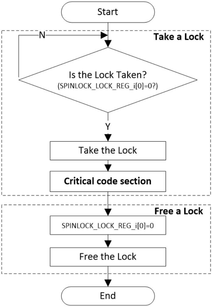
A typical application diagram of the spinlock is shown below:
16.7.2 Features
The spinlock supports the following features:
- APB2 interface with 32-bit data width
- Up to 32 lock units
- Optional interrupt signal for unlock notification
16.7.3 Functional Description
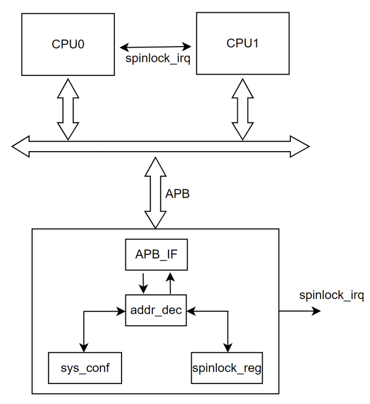
The CPU accesses the spinlock through the APB interface to read and write internal registers for lock and unlock operations. When a spinlock is unlocked, it can optionally generate an IRQ signal to the CPU.
The functional block diagram of the spinlock is shown below:
- After reset, all spinlock units default to the unlocked state.
- Before using a spinlock, the CPU should read
SPINLOCK_STATUS_REGto obtain the status of all spinlock units.
For a spinlock unit in the unlocked state:
- The corresponding
SPINLOCKN_LOCK_REG(N = 0to31) holds0. - Reading this register returns
0and sets the register to1, placing the spinlock unit in the locked state. - At the same time,
SPINLOCK_STATUS_REGis updated.
For a spinlock unit in the locked state:
- The corresponding
SPINLOCKN_LOCK_REG(N = 0to31) holds1. - Reading this register returns
1. Writing0to the register clears it, returning the spinlock unit to the unlocked state. SPINLOCK_STATUS_REGis updated, and an interrupt is generated.
The state transition diagram is shown below:

16.7.3.1 Operating Modes
The spinlock can be used in two modes:
- Polling Mode
- Interrupt Mode
Polling Mode
- CPU0 repeatedly reads
SPINLOCKN_LOCK_REG(N = 0to31) to acquire a spinlock. - If the corresponding bit is
1, the spinlock unit is locked and occupied by another CPU. - If the corresponding bit is
0, the spinlock unit is unlocked. The read operation sets it to the locked state, and CPU0 then owns the spinlock. - CPU0 executes the critical section, while the corresponding bit in
SPINLOCK_STATUS_REGremains1. - After completing the critical section, CPU0 writes
0to the correspondingSPINLOCKN_LOCK_REG, releasing the spinlock and returning it to the unlocked state.
Interrupt Mode
- CPU0 attempts to acquire a spinlock by reading
SPINLOCKN_LOCK_REG(N = 0to31). If the corresponding bit is1, the unit is locked by another CPU. - CPU0 writes to
SPINLOCK_IRQ_EN_REG, enabling the unlock interrupt for the target spinlock unit. - When the spinlock unit transitions from locked to unlocked, an interrupt is triggered, and the corresponding bit in
SPINLOCK_IRQ_STA_REGis set. - CPU0 enters the interrupt service routine, checks
SPINLOCK_IRQ_STA_REG, confirms that the spinlock is now unlocked, and clears the status bit manually. - CPU0 executes the critical section and, upon completion, writes
0to the correspondingSPINLOCKN_LOCK_REG, releasing the spinlock.
16.7.4 Registers
| Register Name | Offset | Description |
|---|---|---|
| SPINLOCK_LOCK_REG_N | 0x0000 + N * 0x0004 | Spinlock Register N (N = 0 to 31) |
| SPINLOCK_VER_REG | 0x0100 | Spinlock Version Register |
| SPINLOCK_SSTATUS_REG | 0x0104 | System Status Register |
| SPINLOCK_STATUS_REG | 0x0108 | Spinlock Status Register |
| SPINLOCK_IRQ_EN_REG | 0x0110 | Spinlock IRQ Enable Register |
| SPINLOCK_IRQ_STA_REG | 0x0114 | Spinlock IRQ Status Register |
16.7.4.1 Register Description
SPINLOCKN_LOCK_REG
Offset: 0x0000 + N * 0x0004
| Bits | Field | Type | Reset | Description |
|---|---|---|---|---|
| 31:1 | RESERVED | R | 0x0 | Reserved |
| 0 | LOCK_STATUS | R/W | 0x0 | Lock status. Read 0x0: The spinlock is unlocked, and the requester changes it to the locked state.Read 0x1: The spinlock is locked.Write 0x0: The requester changes this spinlock to the unlocked state.Write 0x1: No action. |
SPINLOCK_VER_REG
Offset: 0x0100
| Bits | Field | Type | Reset | Description |
|---|---|---|---|---|
| 31:0 | VERSION | R | 0x312E_3030 | Spinlock version |
SPINLOCK_SSTATUS_REG
Offset: 0x0104
| Bits | Field | Type | Reset | Description |
|---|---|---|---|---|
| 31:0 | SYSTEM_STATUS | R | 0x0000_0020 | System status. A value of 32 indicates that this module contains 32 spinlocks. |
SPINLOCK_STATUS_REG
Offset: 0x0108
| Bits | Field | Type | Reset | Description |
|---|---|---|---|---|
| 31:0 | SPINLOCK_STATUS | R | 0x0 | Spinlock status. Bit n = 1 indicates that spinlock n is locked. This register is updated automatically. |
SPINLOCK_IRQ_EN_REG
Offset: 0x0110
| Bits | Field | Type | Reset | Description |
|---|---|---|---|---|
| 31:0 | SPINLOCK_INTR_ENABLE | W/R | 0x0 | Spinlock interrupt enable. Bit n = 1 indicates that an IRQ for spinlock n is generated when the spinlock changes from locked to unlocked. |
SPINLOCK_IRQ_STA_REG
Offset: 0x0114
| Bits | Field | Type | Reset | Description |
|---|---|---|---|---|
| 31:0 | SPINLOCK_STATUS | W/R | 0x0 | Spinlock interrupt status. Bit n = 1 indicates that an IRQ for spinlock n has been generated. Write 1 to clear the interrupt. |
16.7.5 Programming Model
16.7.5.1 Polling Mode
Unlock → Lock
- Read
SPINLOCK_STATUS_REG(base + 0x108) →0x0(all spinlocks are in the unlocked state). - Sequentially read
SPINLOCKN_LOCK_REG(base + 0x000 + N × 0x4,N = 0to31) → returns0x0(this operation changes the spinlock from unlocked to locked). - Read
SPINLOCKN_LOCK_REG(base + 0x000 + N × 0x4,N = 0to31) again → returns0xFFFFFFFF(this operation verifies that all spinlocks are in the locked state).
Lock → Unlock
- Read
SPINLOCK_STATUS_REG(base + 0x108) →0x1(the spinlocks are in the locked state). - Sequentially write
0x0toSPINLOCKN_LOCK_REG(base + 0x000 + N × 0x4,N = 0to31) ←0x0(this operation changes the spinlock from locked to unlocked). - Read
SPINLOCK_STATUS_REG(base + 0x108) →0x0(all spinlocks are now unlocked).
16.7.5.2 Interrupt Mode
- Write
0x1toSPINLOCK_IRQ_EN_REG(base + 0x110) ←0x1(enable the interrupt forspinlock[0]). - Read
SPINLOCKN_LOCK_REG(base + 0x000 + N × 0x4,N = 1) →0x0(spinlock[0]changes from unlocked to locked). - Write
0x0toSPINLOCKN_LOCK_REG(base + 0x000 + N × 0x4,N = 1) ←0x0(spinlock[0]changes from locked to unlocked). - The CPU receives the corresponding interrupt.
Write
0x0toSPINLOCK_IRQ_STA_REG(base + 0x114) ←0x0(clear the interrupt status bit forspinlock[0]).