9. SPI
9.1. Introduction
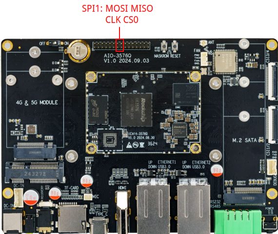
SPI is a high-speed, full-duplex, synchronous serial communication interface for connecting microcontrollers, sensors, storage devices, etc. The AIO-3576JQ development board provides the SPI interface, and the specific position is as follows:
9.2. How SPI works
SPI works in a master-slave mode, which typically has one master device and one or more slave devices, requiring at least four wires, respectively:
CS		    slice selection signal
SCLK		clock letter
MOSI		master device data output and slave device data input
MISO		master device data input and slave device data output
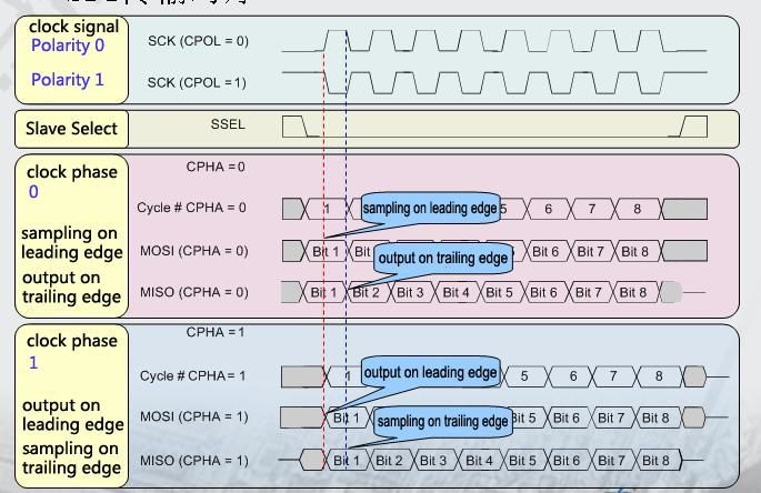
The Linux kernel uses a combination of CPOL and CPHA to represent the four working modes of the current SPI:
CPOL=0,CPHA=0		SPI_MODE_0
CPOL=0,CPHA=1		SPI_MODE_1
CPOL=1,CPHA=0		SPI_MODE_2
CPOL=1,CPHA=1		SPI_MODE_3
- CPOL : Represents the state of the initial level of the clock signal, 0 is the low level and 1 is the high level.
- CPHA : Is sampling along which clock, 0 is sampling along the first clock and 1 is sampling along the second clock.
The waveforms of SPI’s four working modes are as follows:
9.3. Interface usage
Linux provides a SPI user interface with limited functionality. If IRQ or other kernel driver interfaces are not required, consider using spidev interface to write user-level programs to control SPI devices. The corresponding path in the AIO-3576JQ development board is /dev/spidev1.0.
spidev corresponding driver code is kernel-5.10/drivers/spi/spidev.c.
The config in the kernel needs to select SPI_SPIDEV:
 │ Symbol: SPI_SPIDEV [=y]
 │ Type  : tristate
 │ Prompt: User mode SPI device driver support
 │   Location:
 │     -> Device Drivers
 │       -> SPI support (SPI [=y])
 │   Defined at drivers/spi/Kconfig:684
 │   Depends on: SPI [=y] && SPI_MASTER [=y]
DTS configuration like follows:
&spix{
status = "okay";
max-freq = <50000000>;
spidev1: spidev@00{
compatible = "rockchip,spidev";
status = "okay";
reg = <0x0>;
spi-max-frequency = <50000000>;
};
};
Please refer to kernel-5.10/Documentation/spi/spidev.rst for detailed instructions.
9.4. FAQs
9.4.1. Q1: SPI data transfer exception?
A1 : Make sure the IOMUX configuration of SPI 4 pins is correct. Confirm that when TX sends data, TX pins have normal waveform, CLK frequency is correct, CS signal is pulled down, and mode matches the device.