Product Specifications and Components
Server Specifications
| Item | Specification |
|---|---|
| Server Form Factor | 1U rack-mount server |
| Compute Node Model | Supports 8 distributed compute nodes |
| Display Interface | 1080P HDMI interface |
| USB | 2 USB 3.0 ports |
| Network Interfaces | - 2 × 10 Gbps SFP+ shared network ports - 1 × 10/100/1000 Mbps RJ45 shared network port |
| Expansion Hard Drive | 1 × 3.5-inch/2.5-inch SATA3.0 SSD drive bay (hot-swappable; the BMC can operate the drive directly, and compute sub-nodes can indirectly access the drive through the network sharing provided by the BMC) |
| Indicators and Buttons | - 8 compute node system indicators - 1 BMC system indicator |
| Fans | 6 redundant fans |
| System Management | - Adapted to the aBMC management system (supports Redfish, VNC, NTP, advanced monitoring, and virtual media) - 1 × 10/100/1000 Mbps RJ45 management network port |
| Security Features | - Administrator password - Fault alarms - Emergency recovery mode |
Environmental Specifications
| Item | Specification |
|---|---|
| Temperature | - Operating temperature: 5℃ to 40℃ (41℉ to 104℉) - Storage temperature (24H): -40℃ to +65℃ - Storage temperature (within 3 months): -30℃ to +60℃ (-22℉ to +140℉) - Storage temperature (within 6 months): -15℃ to +45℃ (5℉ to 113℉) - Storage temperature (within 1 year): -10℃ to +35℃ (14℉ to 95℉) - Maximum temperature change rate: 20℃ (36℉)/hour, 5℃ (9℉)/15 minutes |
| Relative Humidity (RH, non-condensing) | - Operating humidity: 8% to 90% - Storage humidity (within 3 months): 8% to 85% - Storage humidity (within 6 months): 8% to 80% - Storage humidity (within 1 year): 20% to 75% - Maximum humidity change rate: 20%/hour |
Physical Specifications
| Item | Specification |
|---|---|
| Dimensions (H×W×D) | Chassis: 44.4mm (1U) × 417.3mm × 490.0mm |
| Installation Dimension Requirements | Can be installed in a general-purpose cabinet that complies with the IEC 297 standard: - Width 19 inches - Depth 800 mm or more The rail installation requirements are as follows: - Telescopic rails: the distance between the front and rear square-hole rails of the cabinet ranges from 543.5 mm to 848.5 mm |
| Weight (Fully Configured) | - Net weight: 6.7kg - Packaging material weight: 8.9kg |
| Power Consumption | The power consumption of the whole server varies depending on the quantity and types of the compute units installed. The following are reference values: - Standby power consumption: 300 W - Maximum power consumption: 430 W |
| Power Supply | - The power module does not support hot swapping - The recommended current ratings of the external power air circuit breaker connected to the server are as follows: - AC power: 32 A - DC power: 63 A - The power supply wattage should be greater than the maximum power consumption, with a margin of no less than 50 W |
Components
Front Panel Buttons and Indicators
| Marking | Indicator/Button | Status Description |
|---|---|---|
| 1-8 | Compute node status indicator | - Green (steady on): the compute node has powered on normally. - Off: the compute node is not powered on. |
| OTG | TYPE-C | A USB drive can be used to perform an OTG upgrade of the BMC. |
Network Interfaces
| Marking | Interface Name | Description |
|---|---|---|
| SFP+1 / SFP+2 | SFP+ ports | - The default rate of the 10G optical ports is 10 Gbps. - In a gigabit network environment, manually switch to 1 Gbps. |
| GE | RJ45 | - Gigabit Ethernet port, 1000/100/10 Mbps auto-negotiation. |
| GE M | RJ45 | - Used as the BMC management network. - 1000/100/10 Mbps auto-negotiation. |
Display Interface
| Marking | Interface Name | Description |
|---|---|---|
| HDMI | HDMI interface | - HDMI output directly from the BMC. - Resolution 1080P. |
Hard Drives and Indicators
Hard Drive Location

Hard Drive Configuration
| Configuration | Maximum Number of Hard Drives | Management Method for Ordinary Hard Drives |
|---|---|---|
3.5-inch (or 2.5-inch) hard drive passthrough configuration
|
1 (SATA drive) | SATA output directly from the BMC |
SATA Hard Drive Indicators
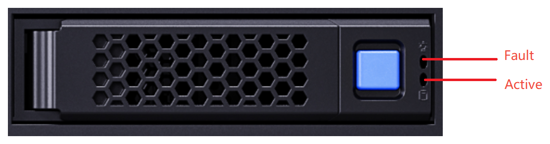
| Hardware Active Indicator (green indicator) | Hardware Fault Indicator (yellow indicator) | Management Method for Ordinary Hard Drives | Handling Steps and Description |
|---|---|---|---|
| Steady on | Off | Drive present | No action required |
| Blinking (4 Hz) | The drive is in a normal read/write state or in the rebuilding primary drive state | ||
| Steady on | Blinking (1 Hz) | The drive is being located by the BMC | |
| Blinking (1 Hz) | The drive is in the rebuilding secondary drive state | ||
| Off | Steady on | The drive has been removed |
1. Check whether the drive is present 2. Check whether the drive is faulty |
| Steady on | Drive failure |